|
|
USER'S INSTRUCTION
Attention:
.
Turn off power before carrying out any maintenance.
. Please handle carefully and avoid abnormal vibration and
shock.
. The dust-proof label on the side of frame must be tear off
clearly, if side- mounted auxiliary contact block or mechanical
interlock is used.
. To dismantle the magnetic contactors which is mounted by
DIN 35mm rail, right“-”screwdriver shall be applied and
handled in running direction.
. A minimum clearance of 8mm and a minimum creepage distance
of 12mm has to be ensured by the installation.
1. Service Environment
1.1 Operational Temperature: -20°c~50°c.
1.2 Storage Temperature: -40°c~70°c.
1.3 Relative Humidity: 45%~85%.
1.4 Altitude: below 2000m.
2. Installation and wiring
2.1 Ensure that the specifications (Rated power, arrangement
of auxiliary contact, rated coil voltage and frequency) meet
the requirements.
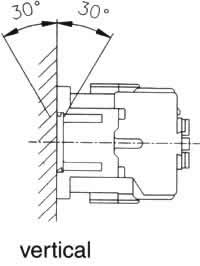
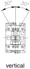
2.2 Mounting positions shall be within the rages specified
below.
2.3 Select appropriate conductor and tighten with appropriate
torque with right tool.
2.4 Tightening torques for contactors are given below:
|
  |
Type |
Item |
Screw/blot |
Tighting torque (kgf.cm) |
TC11 |
Main Terminal |
M3.5 |
8~12 |
TC16 |
Main Terminal |
M3.5 |
8~12 |
TC21 |
Main Terminal |
M4 |
12~20 |
TC30/35/40 |
Main Terminal |
M5 |
20~25 |
TC50/60 |
Main Terminal |
M6 |
35~40 |
All Series |
Main Terminal |
M3.5 |
8~12 |
|
|
|
|
Tightening torque shall be within the values
given above to avoid deteriorating the screws.
3.Maintenance:
3.1 Turn off power before conducting any
maintenance.
3.2 Disconnect the wires in sequence.
3.3 Dismantle contactor as required for maintenance.
3.4 Assemble and connect the contactor in reverse procedures
conducted in steps 3.3and 3.2.
3.5 Check the contactor in a good condition.
4.Replacement of the coil:
Follow the instructions if replacement of the coil
is carried out.
4.1 Dismantle the contactor in appropriate means.
4.2 Replace the coil to requested coil.
4.3 Assemble the contactor in a reverse sequence conducted
in step 4.1.
4.4 Check that the contactor can be operated normally.
|
|
|
|