|
|
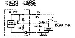
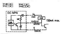
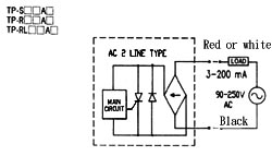
| ・Output stage circuit diagrams |
 |
|
 |
The dashed line express transistor |
| ・The general characteristics of proximity switch |
| .correction coefficient |
|
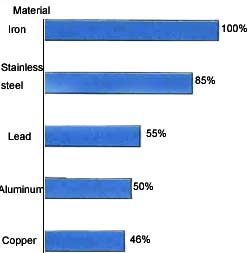
| The correction chart of pick-up distance for non-iron metal, (But the correction factor has no an absolute value.) |
The effect of the electric plating (reference data). The percentage of sensing distance of plating and unplating sensing objects. |
 |
Basic material |
Iron |
Bronze |
The type of plating
|
Unplating |
100 |
100 |
Zn from 5 to 15μ |
From 90 to 120 |
From 95 to 105 From 95 to 105 From 95 to 105 From 95 to 105 |
Cd from 5 to 15μ |
From 100 to 110 |
From 95 to 105 |
Ag from 5 to 15μ |
From 60 to 90 |
From 95 to 105 |
Cu from 10 to 15μ |
From 70 to 95 |
From 95 to 105 |
Cu from 5 to 15μ |
----- |
From 95 to 105 |
|
Cu (from 5 to 10μ)+Ni (10 To 20μ) |
From 75 to 95 |
------ |
|
Cu (from 5 to 10μ)+Ni (10μ) +Cr(0.3μ) |
From 75 to 95 |
------ |
|
| .Response frequency |
| “Reponse frequency” refers to the frequency of outputs from the proximity switch |
| per second in response to the movement of each target when brought closer to |
| the switch.The method of measurement is outlined below. |
|
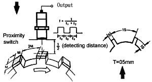
| .To increase sensing speed of the metal object with gear shape, the size of the |
| sensing object should be bigger than the standard object. In the meantime, there |
| should have enough pace between two gears (as shown in above figure). The |
| response frequency will be reduced. If the width of gear face was decreased and |
| the length of gear was narrowed. |
|