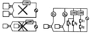
| . Series connection |
| The proximity switches cannot normally be connected in series. If such an arran- |
| gement is necessary, it isrecommended to connect switch in series through a |
| relay. |
|
| .Parallel connection |
| In general, two or more parallel-connected proximity switches cannot be used in |
| an OR circuit. |
| Proximity switches A and B in the above example can be used in a parallel conn- |
| ection only when they are not required to operate simultaneously and the load is |
| nor required to be hold. In this case, however, note that the leakage current |
| increases in proportion to the number of proximity switches connected proximity |
| switches. A and B cannot be used in a parallel connection when they are required |
| A and B cannot be used in a parallel connection when they are required to |
| operate simultaneously to hold the load, Namely, when holding the load by ope- |
| rating switches A and B simultaneously, upon turning on switch A, the voltage |
| at both ends of the switch A(B) drops to about 10V and the load current flows |
| through the switch A. when the target accesses to switch B, since the voltage |
| of both ends of the switch B is 10V, the switching elements of switch B may fail |
| to operate due to insufficient voltage. Upon turning off switch A, since the voltage |
| at both ends of the switch A(B) rises to the supply voltage, switch B turns on at |
| this moment. At this time, there is a moment when both switches A and B turn |
| off(approximately 10ms) and the load is reset momentarily. For this reason,the |
| proximity switches are required to be used through relays to hold the load con- |
| nected. |